Skip to content





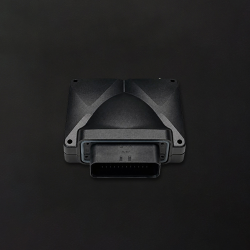
Description
Wiring notes
- Battery supply: pin 1. Ground: pin 35.
- 5 V supply output: pin 6 provides up to 200 mA for sensor power. Do not exceed the maximum rated load.
- Low side outputs: pins 2 to 5 switch to ground. Use them to control relays or other suitable low current loads. Do not connect high current pumps, fans or compressors directly to these outputs.
- Pull up: analog and digital inputs support a switchable 5 V pull up where applicable. Analog input pull up resistance is 10 kΩ. This can be used with switches to ground and compatible resistive sensors.
- Digital inputs (pins 24–27): standard threshold ≈3.0 V rising / 2.4 V falling; low ≈1.9 V / 1.3 V. Pulses shorter than the glitch filter (default 1,000 ns) are ignored.CAN: all devices on the same CAN bus must use the same nominal bit rate. Elite X uses 500 kbit/s as the default setting.
- Enable the 120 Ω termination only when Elite X is located at one physical end of the CAN bus.
- PWM outputs: pins 21 and 22. Enable the PWM output stage in the configuration before using these pins.
- Cameras (pins 28–32): the video switch starts powered down. Turn on device power and the output, then pick the camera.
For More Details View Product Manual.